
Multi-Step Drilling for Thick PCBs: Process and Quality Considerations
How board construction, entry and backup materials, controlled drilling, and inspection affect deep holes in thick multilayer PCBs.
Thick printed circuit boards can require mechanically drilled holes that are deep relative to their finished diameter. The drill must maintain position, remove chips, and leave a hole wall suitable for cleaning and plating. Hole aspect ratio describes the relationship between board thickness and hole diameter, but no single number establishes whether every material and construction is manufacturable.
Why Thick Boards Need a Drilling Review
A deep, narrow hole increases the importance of drill rigidity, chip evacuation, registration, and exit quality. Excessive tool deflection or debris can affect hole position and the condition of resin and copper at the wall. These features matter beyond drilling because a plated through-hole also depends on hole-wall preparation and consistent copper deposition.
The review starts with finished board thickness, finished hole size and tolerance, laminate system, copper distribution, layer registration, hole function, and plating requirement. The drilling route must be matched to the actual board construction rather than copied from a generic speed-and-feed table.
What “Multi-Step Drilling” Can Mean
For a difficult deep hole, a qualified process may divide the cutting action into controlled advances and retractions to help clear chips. Another staged approach for an exceptionally thick board may drill from both sides after the panel is turned and realigned. These are different methods, and neither is automatically required for every thick PCB. Tool geometry, cycle, stack height, spindle settings, and registration method are selected and validated for the job.
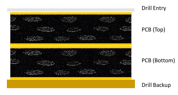
Panel preparation is part of that process. Entry material supports a controlled drill entry; backup material supports the exit side. The fabricator also needs to control tool condition, drill diameter, panel clamping, and, when used, the arrangement of panels in a drill stack. A nominal drill size alone does not prove the finished hole will meet its drawing tolerance.
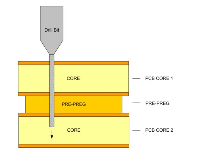
- Define the finished requirement: Record hole function, final size, tolerance, plating, and the relevant layer connections.
- Manage chips and tool wear: Use the fabricator’s qualified drilling cycle and replacement criteria for the laminate and copper build.
- Protect registration: Check the drilled position against inner-layer targets, especially when a two-sided operation is proposed.
- Connect drilling to plating: Treat drilled-hole quality as an input to desmear, metallization, and plated-hole inspection.
Verification After Drilling and Plating
Checks can include tool and hole diameter, hole position relative to inner-layer pads, and representative hole-wall condition. Microsections of a board or process coupon can reveal registration, plated copper distribution, and the connection between a plated barrel and inner-layer copper. The customer drawing and applicable acceptance standard determine the limits for a particular order.
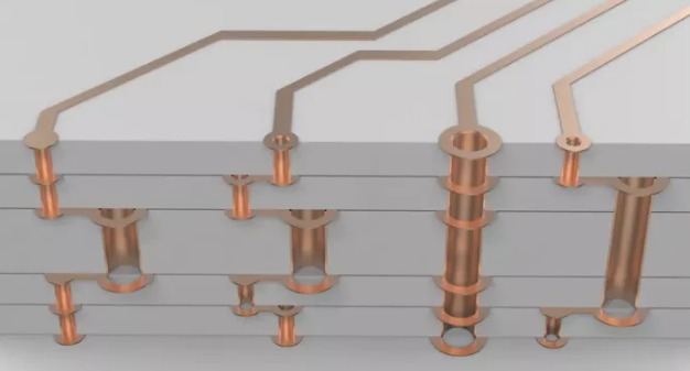
Backdrilling serves a different purpose. It removes an unwanted plated-through-hole stub to improve high-speed signal performance. It should not be treated as the same operation as staged primary drilling of a thick board.
Reliable thick-board drilling depends on a process qualified for the specific design. Early review is particularly useful when a small finished hole is combined with substantial board thickness, heavy copper, tight registration, or demanding plated-through-hole reliability.
BACK TO TECHNICAL ARTICLES