
Rogers RF Laminate Selection: Why One Dk Value Is Not Enough
Process and design Dk, loss, test conditions, copper and construction all matter when comparing Rogers RF laminates.
A dielectric constant (Dk) is an important starting point for an RF PCB material review, but a single number cannot establish that a laminate fits the circuit. Dk affects wavelength, phase delay and impedance; the result also depends on frequency, transmission-line geometry, dielectric thickness and the measurement method. A higher Dk can help reduce circuit dimensions, while a lower Dk can permit wider traces for a target impedance. Neither choice is automatically better.
Process Dk and Design Dk Are Different Inputs
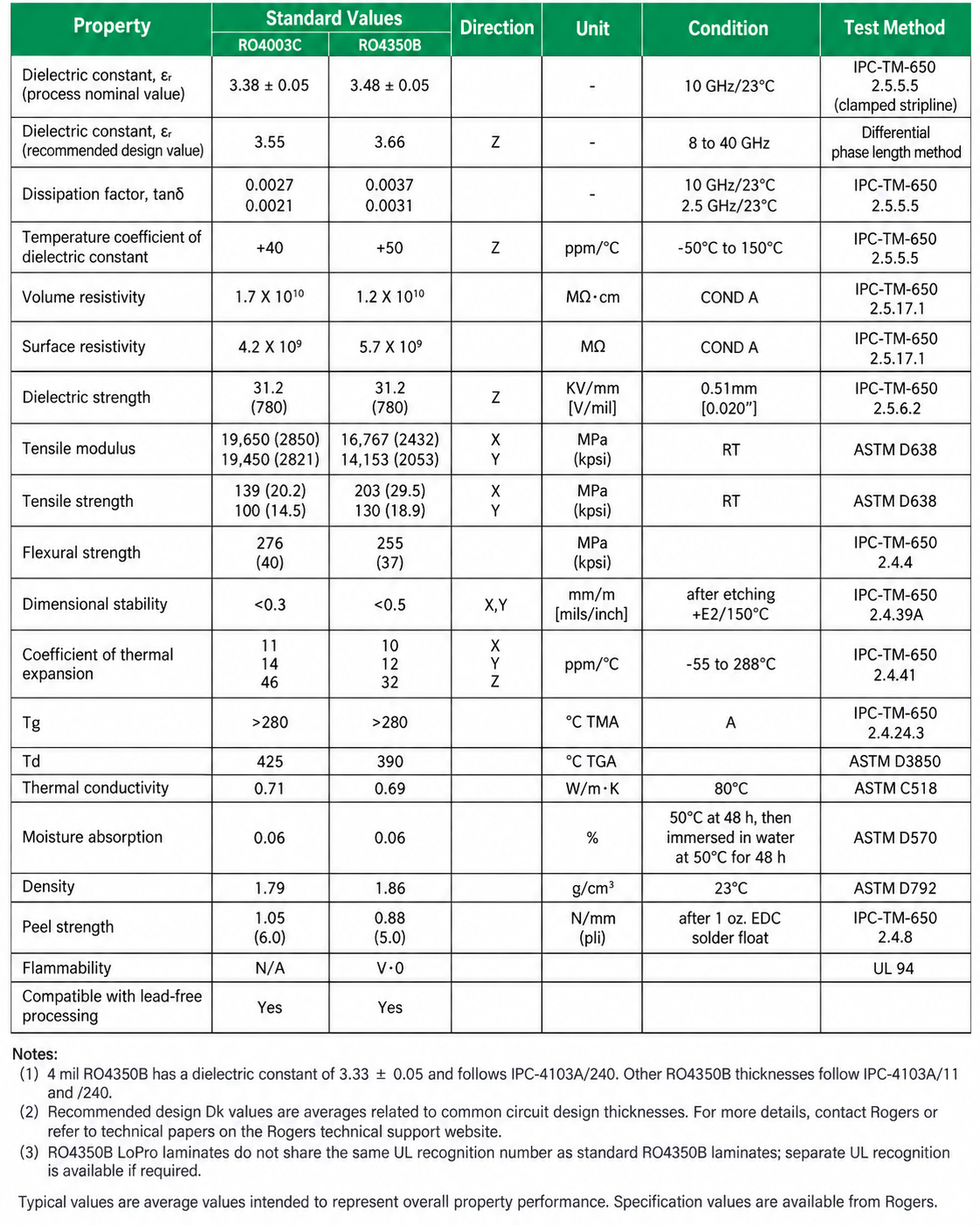
Rogers reports a process Dk measured under a specified material test and a design Dk extracted from circuit behavior for use in RF design models. For example, its RO4000 data lists process Dk of 3.38 ± 0.05 for RO4003C and 3.48 ± 0.05 for RO4350B at 10 GHz and 23 °C. The corresponding recommended design values are 3.55 and 3.66. The same datasheet notes a thickness-specific exception for 4 mil RO4350B. A design value should therefore be selected with its stated method, frequency range and actual material construction in view.
Loss and Test Conditions Matter Too
Dissipation factor (Df) describes the dielectric contribution to RF loss. Total insertion loss also depends on conductor profile, copper construction, line geometry and operating frequency. In the RO4000 data, the typical Df at 10 GHz and 23 °C is 0.0027 for RO4003C and 0.0037 for RO4350B. A useful comparison keeps frequency, temperature and test method visible instead of placing values from unlike conditions side by side.
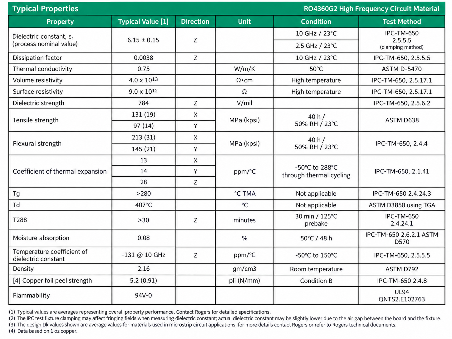
A higher-Dk option may suit a circuit where electrical size matters. Rogers lists RO4360G2 with a process Dk of 6.15 ± 0.15, a design Dk of 6.4 and a typical Df of 0.0038 at 10 GHz. It is not a direct replacement for a lower-Dk laminate: impedance geometry, loss, stackup and fabrication requirements need to be checked together.
Select the Grade and Construction for the Application
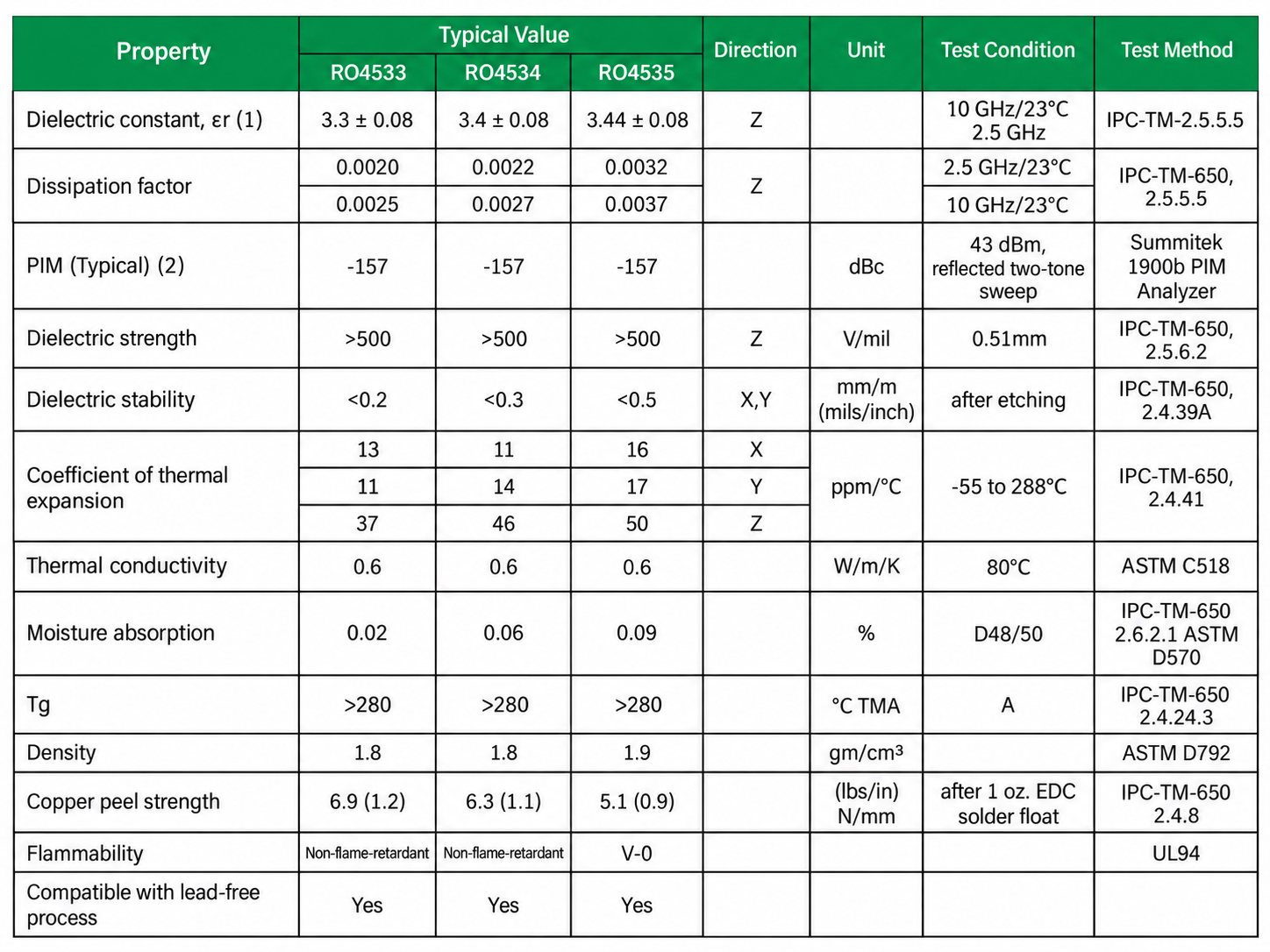
The RO4500 antenna-grade series further shows why a family name is not one material value. Its RO4533, RO4534 and RO4535 grades have different Dk and Df figures, and their flame-rating options differ. The intended antenna geometry, operating band, laminate thickness, copper foil and required qualifications all influence the choice. For a project-specific material and hybrid stack-up review, see RF and microwave PCB manufacturing.
What to Send for a Rogers PCB Quotation
- Specified materials and substitution: State the exact laminate and bondply grades for each RF layer, the operating band, and whether engineering may propose an alternative. Share the Dk and Df assumptions and their test conditions where available; a matching nominal Dk is not approval of a substitute.
- Stack-up and hybrid construction: Supply layer order, RF and FR-4 material placement, dielectric and bondply thickness, copper foil and surface profile, finished thickness and material tolerances. Flag dimensional, thermal, drilling, plating, lamination, assembly or flame-rating requirements that affect material choice.
- Impedance and verification: List targets and tolerances with routing and reference layers, relevant circuit geometry, and any coupon, test or report requirements. The controlled-impedance stack-up guide explains these inputs.
- Matching file revisions: Send Gerber, NC Drill, stack-up drawings and fabrication notes with the same part number, revision and release date. Use the PCB RFQ file checklist for the general data package.
- Quotation and acceptance: Provide quantity, target delivery timing and any special inspection or acceptance requirements. Material availability and manufacturing feasibility are confirmed for the actual project.
The tables above are reference excerpts, not guaranteed finished-board limits. The current Rogers datasheet and the qualified fabrication stackup should govern the released design. A matching nominal Dk alone does not establish equivalent circuit or manufacturing behavior. For a file-based review and quotation, request an RF PCB engineering review.
BACK TO TECHNICAL ARTICLES